Types of Ion Detector for Mass Spectrometry
A key element to all mass spectrometry systems is the type of detector used – but what are the different types?

Complete the form below to unlock access to ALL audio articles.
What are the common types of ion detector for mass spectrometry?
A key element to all mass spectrometry (MS) systems is the type of detector1 used to convert a current of mass separated ions into measurable signal. Different types of detectors are used depending upon factors including dynamic range, spatial information retention, noise and suitability to the mass analyzer. Some of the commonly used types include electron multipliers (EM), Faraday cups (FC), photomultiplier conversion dynodes and array detectors. In this article, we consider these detectors.
Contents
Photomultiplier conversion dynode
- Array detectors for simultaneous measurement of several ions of different m/z
- Array detector for position-sensitive ion detection
Electron multipliers (EM)
An immense advantage of EM2 detectors is that—when calibrated properly—they are noiseless and single ion counting is possible.
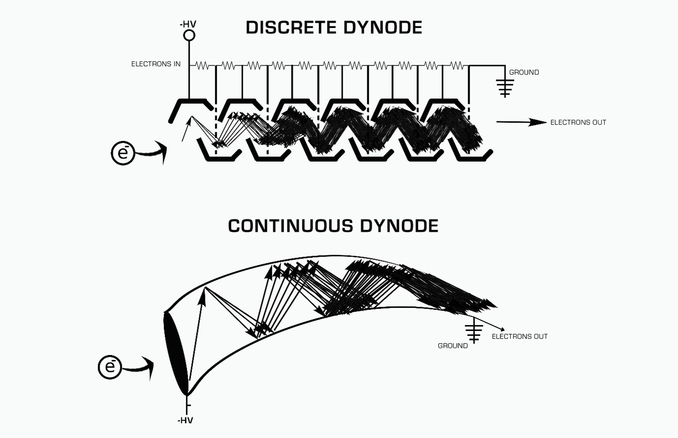
The essence of an EM is a serial connection of discrete metal plates called dynodes that amplifies a current of ions by a factor of ~108 into a measurable current of electrons. When a single secondary ion enters the EM, it is stopped by the first conversion dynode. The energy of impact is dissipated in part by ejection of electrons from the dynode material, creating an electrical charge. Additional electrons are ejected by a cascade process through subsequent dynodes. At the final dynode the accumulated charge is measured as a voltage pulse. The is shown schematically in Figure 1.

Figure 1: Schematic diagram illustrating how a detected incoming ion is converted into a measurable signal using an EM detector. Credit: Nikob7, recreated under the Creative Commons Attribution-Share Alike 4.0 International license.
The magnitude of the voltage pulses resulting from the impacts of a succession of secondary ions is distributed stochastically. The pulse height distribution on these types of detectors can be measured and two distinct regions noted. The high signal that is observed at the low end of the distribution decreasing to a minimum results from electronic noise in the detector system. Following this minimum, an increasing signal with a broad distribution is observed which represents the measured ion current. By setting a threshold to eliminate the noise, these multipliers can effectively count single ions with a dynamic range of 106 Hz. Beyond this count rate, the detector will begin to suffer from two different phenomenon. The first is a “dead time” effect, which refers to that amount of time the detector is in essence not functioning while it is processing signals already received (measured in ns). The second is a quasi-simultaneous arrival effect, where two ions strike the conversion dynode of the electron multiplier at once but it is only recognized as a single ion.
Another type of detector that is commonly used and strongly related to the EM is the channeltron.3 But rather than using a series of discrete metal plates for dynodes, it is composed of a single continuous curved surface that mimics the cascade effect for signal amplification used in discrete dynode electron multipliers.
Faraday cup (FC)
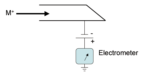
FC detectors4 are relatively simple and cheap devices. Their main strength is the ability to measure higher ion currents where the EM struggles. It consists of a hollow conducting electrode connected to ground through a high resistance. The ions hitting the collector cause a flow of electrons from ground through the resistor and the resulting potential drop across the resistor is amplified. The elementary charge on a single ion is 1.6 x 10⁻¹⁹ C. Therefore, a count rate of 1 x 10⁶ c/s (about the upper realistic limit for EM detector usage) would produce a current of 1.6 x 10⁻¹³ A (Figure 2). Even with a resistance as high as 1011 W connected to ground, the amplifier must be able to detect a potential drop of 16 mV. Thus, measuring lower currents will become more difficult as the thermal and electronic noise in the resistor and amplifier circuitry will have a large effect on precision. Often these components will be enclosed within an evacuated, thermally controlled chamber.

Figure 2: Schematic diagram of a Faraday cup ion detector. Credit: K. Murray, recreated under the Creative Commons Attribution-Share Alike 3.0 Unported license.
Photomultiplier conversion dynode
In a photomultiplier conversion dynode detector,5 the ions initially strike a dynode which results in electron emission. The electrons produced then strike a phosphor screen which in turn releases photons. The photons then pass into the multiplier where amplification occurs in a cascade fashion – much like with the electron multiplier. The main advantage of using photons is that the multiplier portion of the detector can be kept sealed in a vacuum, preventing contamination and greatly extending the lifetime of the detector.
Figure 3: Schematic diagram of a photomultiplier conversion dynode detector. Credit: Kkmurray, recreated under the Creative Commons Attribution-Share Alike 3.0 Unported license.
Array detectors
The first detector on a mass spectrometer was indeed an array detector – photographic film. Since that time, array detectors have evolved into a variety of types using different principles. Array detectors can cover a broad range of detector types and systems6 but can be generally broken down into two categories:
- detectors that can measure many ions of differing mass-to-charge ratio (m/z) values simultaneously
- detectors that are position sensitive
Sometimes a single type of detector can fulfil both requirements to greater or lesser degrees.
Array detectors for simultaneous measurement of several ions of different m/z
Perhaps the simplest “array” detector can be found on those MS systems that combine both EM and FC detectors. For isotope ratio measurements, the most abundant isotope can be measured using the FC, while the weaker abundant isotope, yielding a much smaller ion current, is more suited for measurement on an EM.
Another form of detector array that may be commonly found in MS instruments that employ a multicollection system consists of several EMs and/or FCs that can be moved to measure ions of specific m/z values. An example is seen in Figure 4 for the nanoscale secondary ion mass spectrometer (NanoSIMS),7 which has 6 movable and 1 fixed EM detectors, permitting simultaneous analysis of 7 different masses. These are associated with mass spectrometers that disperse ions according to their m/z value, such as in magnetic sector instruments.

Figure 4: Schematic diagram of double focusing magnetic section mass spectrometer incorporating a multicollector system and static magnetic field – the nanoscale secondary ion mass spectrometer (NanoSIMS).
Array detector for position-sensitive ion detection
Array detectors for position sensitive measurements8 have used microchannel plates (MCP) for many years. The array consists of upwards of 106 microscopic glass channels, each 5–50 mm in diameter, bound together in a honeycomb-type array and electrically connected. Each channel operates as a continuous-dynode EM with a gain in the order of 104. To increase gain, 2 or 3 MCP detectors can be placed in series, resulting in final gains from 106 to 108. Since the secondary electrons are confined to the channel from which they originated by the original ion impact, it is possible to obtain spatial resolution from the MCP, provided a means of recording the final electron cloud distribution is available. This is often accomplished using a phosphor screen and some form of camera, such as a charge-couple device (CCD) array system or other digital technology. Though very useful for position sensing of the ions, it provides more qualitative than quantitative information unless extremely well and frequently calibrated as aging effects are an issue (for both the MCP and the phosphor screen).
The resistive anode encoder (RAE) detector9 is a form of a charge division detector commonly used in imaging MS, particularly secondary ion mass spectrometry (SIMS). As with charge division detectors in general, they function by using an anode structure to intercept and divide amongst several sensors the electron cloud originating from an MCP. Mathematical algorithms based on the strength of the signal received at each of the sensors can be performed to determine the original position of the ion current leading to the measured charge cloud. In the specific case of the RAE, since the anode material is made of a resistive semiconductor, the signal used is the voltage produced on this material by the electron cloud. The main limitations of such devices are their inability to measure simultaneous ion arrivals and thus their dynamic range is limited to about 104-105 Hz.
You can read more about the previous steps in the MS process by following the links below to articles on ionization sources and mass analyzers.
1.
Koppenaal DW, Barinaga CJ, Denton MB, et al. MS detectors. An. Chem.
2005;418A-427A. American Chemical Society
2.
Allen JS. An improved electron multiplier particle counter. Rev. Sci.
Instrum. 1947;18(10):739-749. doi:10.1063/1.1740838
3. Tuithof HH, Boerboom AJH, Meuzelaar HLC. Simultaneous detection of a mass
spectrum using a channeltron electron multiplier array. Int. J. Mass
Spectrom. Ion Phys. 1975;17(3):299-307. doi:10.1016/0020-7381(75)87040-9
4. Brown KL, Tautfest GW. Faraday‐cup
monitors for high‐energy electron beams. Rev. Sci. Instrum. 1956;27(9):696-702.
doi:10.1063/1.1715674
5. Dubois F, Knochenmuss R, Zenobi R. An ion-to-photon conversion detector for
mass spectrometry. Int. J. Mass Spectrom. Ion Proc.
1997;169-170:89-98. doi:10.1016/S0168-1176(97)00210-3
6. Barnes JH, Hieftje GM. Recent advances in detector-array technology for mass
spectrometry. Int. J. Mass Spectrom. 2004;238(1):33-46. doi:10.1016/j.ijms.2004.08.004
7. Nuñez J, Renslow R, Cliff JB, Anderton CR. NanoSIMS for biological
applications: Current practices and analyses. Biointerphases.
2018;13(3):03B301. doi:10.1116/1.4993628
8. Sinha MP, Wadsworth M. Miniature focal plane mass spectrometer with
1000-pixel modified-CCD detector array for direct ion measurement. Rev.
Sci. Instrum. 2005;76(2):025103. doi:10.1063/1.1840291
9. Brigham RH, Bleiler RJ, McNitt PJ, Reed DA,
Fleming RH. Characterization of two resistive anode encoder position sensitive
detectors for use in ion microscopy. Rev. Sci. Instrum. 1993;64(2):420-429.
doi:10.1063/1.1144211


