Mass Analyzers for Mass Spectrometry
Mass analyzers lie at the heart of mass spectrometers, taking the ionized masses and separating them based on their mass-to-charge ratio (m/z).

Complete the form below to unlock access to ALL audio articles.
What are the common types of mass analyzer?
At the heart of any mass spectrometer is the mass analyzer. This component takes the ionized masses and separates them based on their mass-to-charge ratio (m/z). Types include time-of-flight (ToF), quadrupole, magnetic sector, ion trap and Orbitrap mass analyzers or a combination system (tandem mass spectrometry (MS)). In this article, we consider some of the common types of mass analyzers, their advantages and disadvantages.
Time-of-flight (ToF) mass analyzers
One of the most common types of mass spectrometer is the ToF instrument. The basic principle behind ToF mass spectrometers relies on the fact that ions can be separated according to their m/z ratio based on the length of time it takes them to travel through a flight tube of known length to reach a detector. Ions with lower m/z will travel the fastest and arrive at the detector first, while ions with larger m/z will travel the slowest and arrive at the detector last. Owing to the ToF principle, these mass spectrometers are almost always used with a pulsed ion source. It is also for this reason that they are frequently coupled to matrix assisted laser desorption ionization (MALDI) sources as lasers also frequently operate in pulsed mode.
A big advantage of ToF systems is that they acquire in parallel a very wide range of m/z values – data that is always stored and can be retrieved post-analysis. They also have very good mass resolution, particularly when reflectrons are incorporated in the flight tube to compensate for different kinetic energies of analyte ions as illustrated in Figure 1.

Figure 1: Schematic of a ToF system. Animated version available here. Credit: Abigail Koss, TOFWERK.
Quadrupole mass analyzers
Quadrupole mass analyzers consist of two pairs of metal rods equidistant from each other and biased at equal and opposite potentials. These twin potentials contain a fixed direct current (DC) and alternating radio frequency (RF) component, where the strength of the RF component can be varied. Any ion entering the quadrupole will have its trajectory deflected by the potential in a manner that is proportional to its m/z value. At specific RF values, only one specific m/z value will resonate with the field and be able to navigate to the end of the quadrupole and be detected. Ions with other m/z values will collide with the quadrupoles, lose their charge and not be detected. The basic concept is illustrated in the animation in Figure 2.

Figure 2: Animation showing how a quadrupole mass analyzer works. Credit: Abigail Koss, TOFWERK.
Since the separating principle of the quadrupole MS system is straightforward, they are comparatively easier to operate and maintain. Also, the quadrupole is compact in design, robust and relatively inexpensive. Consequently, they are widely adopted as a general-purpose analytical instrument. Furthermore, unlike other MS which requires high vacuum levels, quadrupole MS can adequately function at lower vacuum levels (~ 10-2 to 10-3 Pa). Even if they are interfaced with a gas chromatography (GC) or liquid chromatography (LC) unit, the drop in vacuum level caused by the interface has minimal effect on the mass separation performance, making it the best suited for interfacing with chromatographic techniques.
Advantages of quadrupole systems include good scan speed and sensitivity and a mass range of up to 2,000 m/z. In addition, it allows highspeed polarity switching, which facilitates simultaneous monitoring of multiple selected ions of different polarity. However, it suffers from relatively poor mass resolution when used as a single system and not in tandem with other separation or MS methods.
Magnetic sector mass analyzers
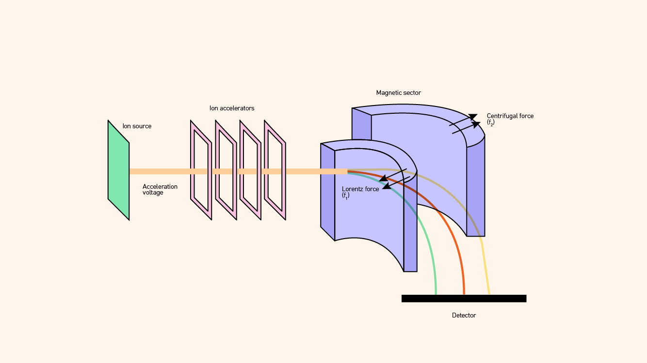
Magnetic sector mass analyzers rely on the fact that magnetic fields can disperse ions in trajectories according to their m/z ratios in a manner that is analogous to how a glass prism disperses light into its various wavelengths or colors (Figure 3). Figure 3: Schematic diagram of a magnetic sector mass spectrometer. Credit: Technology Networks.
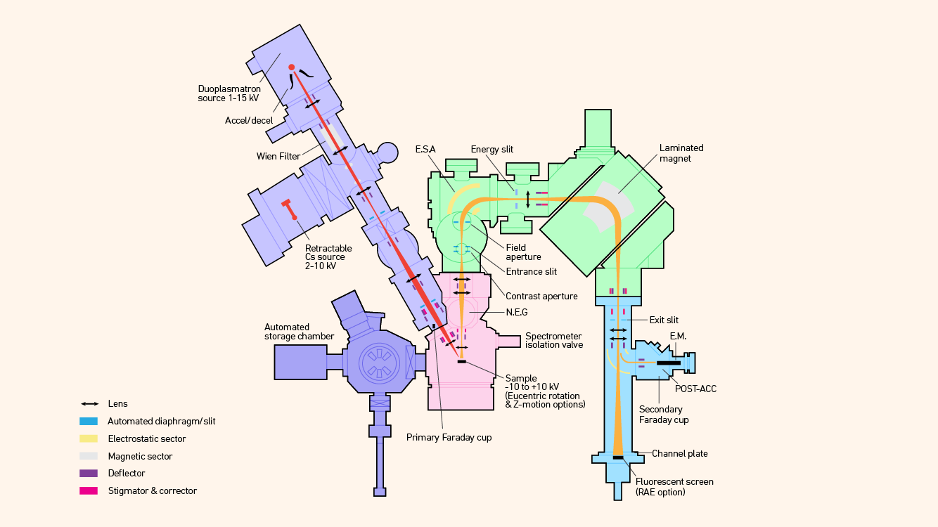
Several variants exist, including the “double focusing” version that incorporates an electrostatic sector to compensate for kinetic energy differences in ions (Figure 4). Others use a multicollector detection system that allows for parallel detection of several masses by using a static magnetic field, rather than by cycling the field, to measure as many masses as desired serially (Figure 5).
 Figure 4: Schematic diagram of a double focusing magnetic sector mass spectrometer including oxygen plasma source and Cs ionization sources. Credit: Technology Networks.
 Figure 5: Schematic diagram of double focusing magnetic section mass spectrometer incorporating a multicollector system and static magnetic field – the nanoscale secondary ion mass spectrometer (NanoSIMS).1 Credit: Technology Networks.
Such systems are characterized by a high sensitivity and mass resolution, but they are expensive and require skilled and experienced operators. It is also necessary to maintain these mass spectrometers under ultrahigh vacuum and so they do not lend themselves well to coupling with separation techniques such as LC.
Ion trap mass analyzers
The principles behind ion trap MS are somewhat similar to the quadrupole but with some key differences. An ion trap generally consists of a ring-shaped electrode sandwiched between two end-cap electrodes. An ionization unit is located at the entrance and a detector at the exit. The ring electrode can be thought of as being somewhat analogous to the entrance and exit of a quadrupole. However, in an ion trap there is usually no voltage to the electrodes as in the quadrupole system, leading to ion movement along the horizontal axis. During analysis, end-cap electrodes are first grounded, then a low RF voltage is applied to the ring electrode. The ions are introduced into the trap in a pulse mode where they are all temporarily trapped inside the electrode. At this point, the ions with varying mass are experiencing stable oscillations within the trap. To detect a specific ion, the RF voltage is gradually increased. As the voltage increases, oscillations of ions of specific m/z ratio become unstable and these ions are discharged through a hole in the end-cap electrode. While quadrupole systems separate and detect masses by allowing oscillating ions to pass through the quadrupole to reach a detector, ion trap systems separate and detect ions by discharging ions with unstable oscillations from the system and into the detector.
Advantages of ion traps are that they are small and relatively cheap and have good sensitivity and mass resolution.
Orbitrap mass analyzers
The Orbitrap borrows technology from many of the other types of mass analyzers. It consists of two electrically isolated cup-shaped outer electrodes facing each other and a spindle-like central electrode that holds the trap together. When voltage is applied between the outer and the central electrodes, the resulting electric field is linear along the axis, while the radial component of the field strongly attracts ions to the central electrode. Ions are injected or pulsed into the volume between the central and outer electrodes tangentially through a slot machined in one of the outer electrodes.
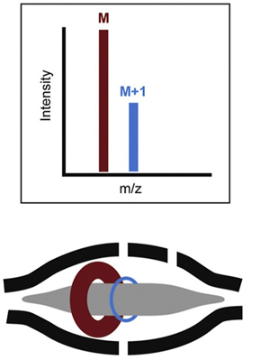
The electric field is increased by ramping the voltage on the inner electrode. Ions get squeezed towards the inner electrode until they reach the desired orbit inside the trap. At that moment, the electric field is held constant and the field becomes static. The injected ions will move with different rotational frequencies but with the same axial frequency. This means that ions of a specific mass-to-charge ratio spread into rings that oscillate or orbit along the inner spindle (Figure 6). With voltage applied between the central and outer electrodes, a radial electric field bends the ion trajectory toward the central electrode while tangential velocity creates an opposing centrifugal force. For a certain set of parameters, the ions remain on a nearly circular spiral, or orbit, inside the trap. Their frequency of rotation is directly related to their m/z value.

Figure 6: Schematic diagram of orbital ion trajectories in an Orbitrap and example resulting mass spectrum. Credit: Adapted from2, reproduced under the Creative Commons Attribution 4.0 International license.
The axial electric field caused by the special conical shape of electrodes pushes ions toward the widest part of the trap. Outer electrodes are then used for current detection. The digitized image current in the time domain is Fourier-transformed into the frequency domain and then converted into a mass spectrum. It is the only method described here that uses an image current rather than some detection device to detect the ions.
The main strengths of the Orbitrap are its relatively small size and the very high mass resolution and mass accuracy that it can achieve.
Tandem mass spectrometry (tandem MS)
In a general sense, tandem MS refers to those hybrid methods involving more than one type of mass spectrometer to increase specificity and/or mass resolving capability. They are commonly referred to as MS/MS techniques in the literature. These systems often include an additional separation technology, such as GC or LC.
Typically:
- An ion formed in an ion source is mass-filtered in the first mass analyzer
- These filtered ions may then undergo some form of reaction in subsequent reaction cells
- The charged products emerging from this cell are then analyzed by the second mass analyzer
The type and quality of data that is obtained can vary greatly depending upon the configuration of the MS/MS system used and the form of reaction performed between the stages of analysis. Glish and Burinsky review several tandem MS variants.3
You can read more about the other main steps in the MS process by following the links below to articles on ionization sources and ion detectors.
1. Nuñez J, Renslow R, Cliff JB, Anderton CR. NanoSIMS for biological applications: Current practices and analyses. Biointerphases. 2018;13(3):03B301. doi: 10.1116/1.4993628
2. Hofmann AE, Chimiak L, Dallas B, et al. Using Orbitrap mass spectrometry to assess the isotopic compositions of individual compounds in mixtures. Int J Mass Spectrom. 2020;457:116410. doi: 10.1016/j.ijms.2020.116410
3. Glish GL, Burinsky DJ. Hybrid mass spectrometers for tandem mass spectrometry. J Am Soc Mass Spectrom. 2008;19(2):161-172. doi: 10.1016/j.jasms.2007.11.013


